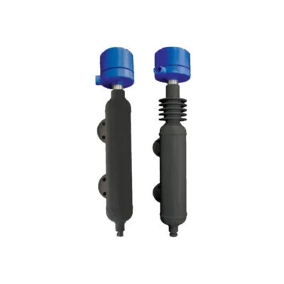
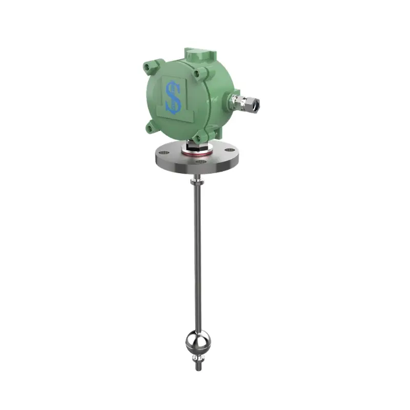
The Shridhan FLX Series comprises Reed Chain Level Transmitters for continuous liquid level measurement and indication.
The float-operated sensor provides continuous level measurement using a magnetic float and closely spaced reed switches, with factory calibration for reliable repeatability.
Available with 4-20mA, HART or RS-485 options, multiple float and stem materials, top, chamber and stilling-well mounting, and measuring ranges up to 3850 mm.
✅ Genuine Shridhan product with manufacturer warranty
✅ ProSens Automation — Coimbatore, Erode & Salem
The Shridhan FLX Series Reed Chain Level Transmitter is a float-operated continuous level transmitter designed for continuous indication and control of liquid levels.
The float and guide-stem assembly uses a magnetic float to actuate a chain of closely spaced glass-encapsulated reed switches and resistors. As the liquid level rises or falls, the float moves along the guide stem and changes the resistance of the reed chain proportionally to the liquid level.
The transmitter electronics convert the sensed resistance into a continuous output signal. The brochure specifies 4-20mA, 4-20mA with HART, RS-485 and voltage-output configurations.
FLX transmitters are factory pre-calibrated, require no field calibration according to the brochure, and are available with customized lengths up to 4 metres.
These features are stated in the introductory FLX section of the manufacturer brochure. :contentReference[oaicite:1]{index=1}
The FLX uses a magnetic float and reed-chain sensing principle. A float moves along a non-magnetic guide stem as the liquid level changes.
Inside the guide tube is a chain of closely spaced glass-encapsulated reed switches and resistors. The magnet inside the float actuates the reed switches as the float moves.
The resulting resistance changes proportionally with float position, operating similarly to a sliding resistance potentiometer. The transmitter electronics then convert this resistance into the required output signal.
| Component | Function |
|---|---|
| Float | Moves with the liquid level and carries the magnetic actuation system. |
| Guide Stem | Provides the guided path for the float. |
| Reed Chain | Closely spaced reed switches and resistors generate a proportional resistance. |
| Transmitter Electronics | Converts the sensed resistance into the selected output signal. |
The operating principle is described on page 3 of the brochure. :contentReference[oaicite:2]{index=2}
| Parameter | Specification |
|---|---|
| Measuring Range | Minimum 300 mm (GSL 400 mm); maximum 3850 mm (GSL 4000 mm) |
| Resolution / Accuracy | Standard ±10 mm / 1 mm; High ±5 mm / 0.5 mm |
| Installation | Top of tank; top mount with stilling well; external chamber; MLI chamber |
| Enclosure | Weather Proof IP67; Ex-Proof IP66, Group IIA, IIB or IIC |
| Conduit Connection | Brass Double Compression Gland; PG gland |
| Probe / Stem | SS304, SS316, SS316L, SS316 with PTFE sleeve |
| Float Material | SS304, SS316, SS316L, PP, PVDF |
| Float Diameter | Ø41 mm, Ø45 mm and Ø63 mm in SS316; Ø46 mm and Ø48 mm in PP/PVDF |
| Process Connection | Flanged / Threaded |
| Output | DC 4-20mA isolated; 1-5 VDC; 2-10 VDC; 4-20mA with HART; RS-485 |
| Wiring System | 2-wire loop powered |
| Maximum Temperature | 120°C for metallic MOC |
| Maximum Test Pressure | 10 kg/cm² for metallic MOC |
| Special Feature | Intrinsically Safe, Explosion Proof IP66 Ex ia, Group IIA/IIB |
The specifications above are taken from the FLX specification table on page 3. :contentReference[oaicite:3]{index=3}
| Output | Configuration |
|---|---|
| 4-20mA | 2-wire loop-powered isolated output |
| 4-20mA + HART | 2-wire output with HART protocol |
| 1-5 VDC | Voltage output |
| 2-10 VDC | Voltage output |
| RS-485 | Digital communication option specified in the general specifications |
| IIOT | Available as an ordering option in the brochure |
The ordering table on page 4 specifically lists 4-20mA, 4-20mA with HART, 1-5 VDC, 2-10 VDC and IIOT output selections. :contentReference[oaicite:4]{index=4}
| Code | Float Material | Float Diameter | Stem Diameter |
|---|---|---|---|
| S1 | SS316 | 41 mm | 12.7 mm |
| S2 | SS316 | 45 mm | 12.7 mm |
| S3 | SS316 | 63 mm | 16 mm |
| S4 | PP | 46 mm | 16 mm |
| S5 | PVDF | 48 mm | 16 mm |
| S6 | SS316 | 52 mm | 12.7 mm |
| S7 | Others | — | — |
These float configurations are listed in the FLX ordering information on page 4. :contentReference[oaicite:5]{index=5}
| Code | Enclosure |
|---|---|
| A | Weather Proof IP67 / Cast Aluminium |
| B | Weather Proof IP67 / Stainless Steel |
| C | Weather Proof IP65 / PP |
| D | Ex-Proof IP66 Group IIA, IIB or IIC / Cast Aluminium |
| E | Ex-Proof IP66 Group IIA, IIB or IIC / Stainless Steel |
| O | Others |
The enclosure options above are taken from the FLX ordering information. :contentReference[oaicite:6]{index=6}
| Type | Options |
|---|---|
| Flanged | 2", 2½" and 3" #150 ANSI; 2", 2½" and 3" Table E; 2", 2½" and 3" Table D; SS/MS/PP options; Others |
| Threaded | 2" BSP and 3" BSP with SS/MS/PP; Others |
These process connection choices are specified in the FLX ordering information on page 4. :contentReference[oaicite:7]{index=7}
| Mounting | Description |
|---|---|
| Top / Internal Mount | Transmitter mounted from the top of the tank. |
| Side / Chamber Mount | Arrangement for side or chamber installation. |
| Inside External Chamber | Transmitter installed inside an external chamber. |
| With Stilling Well | Top mounting arrangement using a stilling well. |
The mounting options are specified in the ordering table and illustrated on page 5. :contentReference[oaicite:8]{index=8}
The FLX is also available with a ferrule arrangement for applications where the measuring range is not fixed or where vessel/tank dimensions are not clearly known.
The ferrule allows adjustment of the measuring range to the desired level by approximately ±300 mm.
| Feature | Details |
|---|---|
| Application | When measuring range or vessel dimensions are not fixed/clearly known |
| Adjustment | Approximately ±300 mm |
| Adjustment Element | Ferrule |
The ferrule arrangement is described and illustrated on page 6 of the brochure. :contentReference[oaicite:9]{index=9}
Where it is not possible or desirable to install the float level transmitter directly onto the vessel, the FLX can be installed in an external chamber.
The chamber arrangement is intended to provide smooth level control irrespective of turbulence in the process vessel and helps prevent accidental damage to the transmitter during shutdown or maintenance.
| Chamber Application | Purpose / Feature |
|---|---|
| Process Isolation | Suitable where process isolation is required. |
| High Pressure / High Temperature | Chamber arrangements are available for these applications. |
| Corrosive Applications | Provides an alternative installation arrangement for corrosive process conditions. |
| Onshore / Offshore | Chamber configurations are available for onshore and offshore installations. |
| Level Measurement | Continuous level measurement. |
| Interface Measurement | Measurement of the interface between two liquids. |
The brochure describes these external-chamber functions and applications on page 7. :contentReference[oaicite:10]{index=10}
| Application | Why FLX Is Used |
|---|---|
| Continuous Tank Level Measurement | Continuous float-operated analog level measurement. |
| Liquid / Liquid Interface | The brochure specifies liquid/liquid interface detection. |
| Sticky or Dirty Liquids | Self-cleaning float construction is specified for sticky or dirty environments. |
| External Chamber Applications | Suitable where direct vessel installation is not possible or desirable. |
| High Pressure / Temperature | Available with appropriate chamber and metallic construction configurations. |
| Corrosive Applications | Multiple stem and float materials are available, including SS and polymer options. |
| Hazardous Areas | Intrinsically safe and explosion-proof configurations are specified. |
The brochure also shows the DLC1001 Level Controller as an option available on request.
The controller is illustrated on page 5 alongside the FLX installation arrangement. :contentReference[oaicite:11]{index=11}
The exact supplied configuration depends on the selected FLX ordering code. The brochure does not provide a separate standard packing list, so accessories and additional controller arrangements should be confirmed when ordering.
The Shridhan FLX Series is available through ProSens Automation for continuous liquid level measurement and control applications.
For correct selection, share the tank dimensions, required measuring range, liquid, specific gravity, temperature, pressure, mounting arrangement, process connection and required output.
ProSens Automation — Coimbatore, Erode & Salem
Shipping available across India.
The FLX Series is a Reed Chain Level Transmitter designed for continuous liquid level measurement using a magnetic float and reed-chain sensing system.
FLX is a continuous level transmitter. Its float position produces a proportional resistance that is converted into an analog output.
The brochure specifies 4-20mA, 4-20mA with HART, 1-5 VDC, 2-10 VDC and RS-485 options. The ordering table also includes an IIOT option.
The general FLX specification gives a maximum span of 3850 mm, with a guided stem length up to 4000 mm.
The specified minimum span is 300 mm, with a guided stem length of 400 mm.
The brochure specifies standard resolution/accuracy of ±10 mm / 1 mm and a high-resolution option of ±5 mm / 0.5 mm.
The general specification lists SS304, SS316, SS316L, PP and PVDF. The ordering information provides specific float configurations using SS316, PP and PVDF.
Yes. The brochure specifically provides external chamber installation for applications where direct vessel mounting is not possible or desirable.
Yes. Liquid/liquid interface detection is listed as a feature, and interface measurement is also identified for the external-chamber arrangement.
Yes. The brochure lists a 4-20mA output with HART protocol as an FLX ordering option.
Yes. The brochure specifies Ex-Proof IP66 enclosure options for Groups IIA, IIB or IIC and also identifies intrinsically safe options.
A ferrule version is available for applications where the measuring range or tank dimensions are not fixed. The brochure states that the ferrule allows adjustment of the measuring range by approximately ±300 mm.